Understanding the Circuit Board Assembly Process: A Complete Guide

The circuit board assembly process is the heart of nearly every electronic device we use today—from smartphones to medical equipment. If you’ve ever wondered how these complex gadgets come to life, it all starts with a precise and highly technical process that transforms raw components into fully functional circuit boards.

In this guide, we’ll break down what the circuit board assembly process is, how it works, and why proper assembly is essential for a device’s performance and reliability.

What Is a Circuit Board?

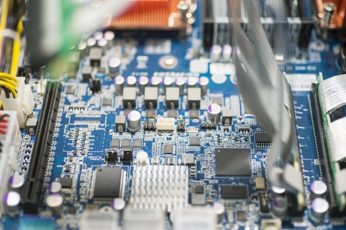
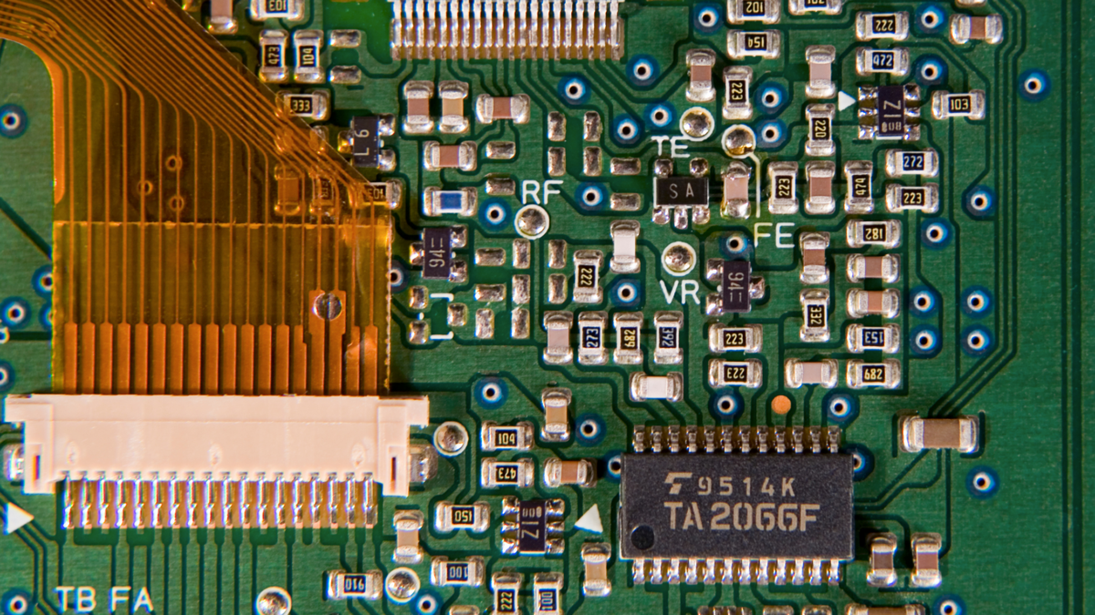
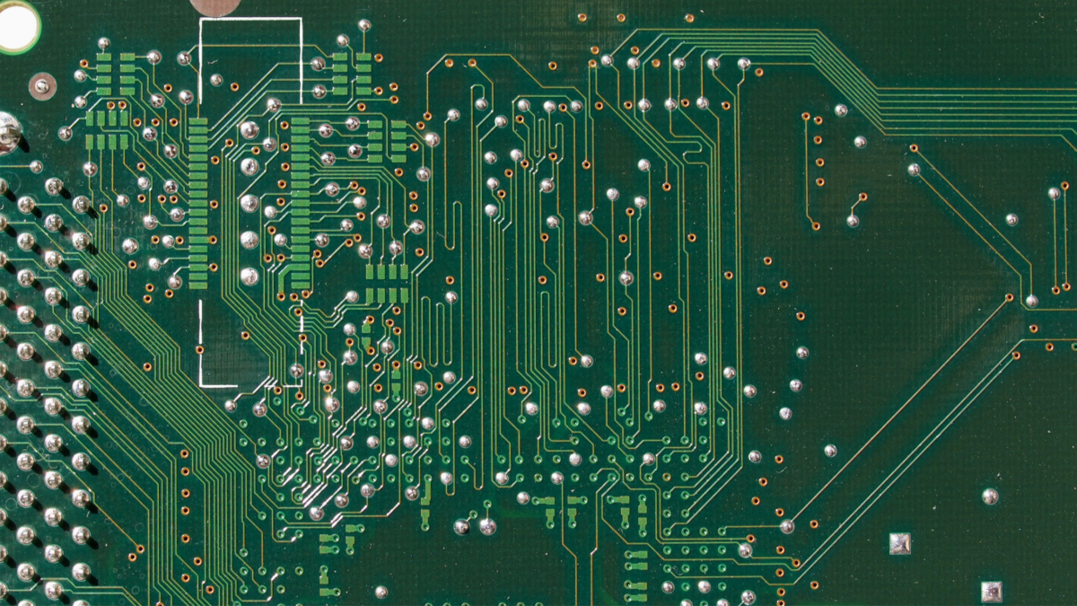
At the core of the circuit board assembly process is the printed circuit board, or PCB. A PCB is a flat, typically green or blue board that holds and connects all the electronic components necessary for a device to function. While it may look like a simple piece of plastic, it’s actually a carefully engineered multi-layered structure composed of copper layers, insulating materials, and a protective coating.

These layers form the foundation of the circuit board assembly process, serving as both the physical platform and the electrical pathway for components like resistors, capacitors, and microchips.

The Layers Behind the Circuit Board Assembly Process

A standard circuit board used in the circuit board assembly process may have anywhere from 2 to 50+ layers, depending on the complexity of the device. These layers include:

  • Top and Bottom Layers: These are the surfaces where most components are mounted during the circuit board assembly process. They also contain antennae in certain applications.

  • Power and Ground Planes: These layers distribute power and grounding across the board.

  • Signal Layers: Internal layers route communication signals between components.

  • Insulation Layers: Fiberglass and epoxy resin insulate the copper layers and prevent electrical shorts.

  • Solder Mask and Silkscreen: The outermost coatings used to protect the copper and guide component placement.

Each part of this multi-layered system plays a critical role in the circuit board assembly process, ensuring electrical functionality and durability.

Step-by-Step: The Circuit Board Assembly Process

Now let’s walk through the key steps involved in the circuit board assembly process:

1. Solder Paste Application

The process begins with applying solder paste to the board using a stencil. This paste helps secure components to the board once heat is applied.

2. Automated Component Placement

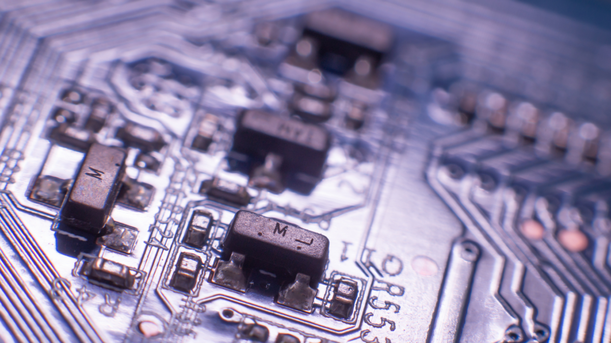
High-speed machines then place components like ICs, resistors, and capacitors on the board with extreme precision—an essential phase of the assembly process.

3. Reflow Soldering

After placement, the board goes through a reflow oven, which melts the solder paste and creates permanent electrical connections.

4. Inspection and Quality Control

The circuit board assembly process includes both visual and automated optical inspections to detect misalignments or soldering defects.

5. Through-Hole Component Insertion (if needed)

Some designs use through-hole components, which are manually or mechanically inserted and soldered into place.

6. Final Testing

Before a board can move on to the product line, it undergoes functional and electrical testing. This stage of the assembly process ensures that every connection works as expected and that the board meets performance standards.

Why the Circuit Board Assembly Process Matters

A reliable assembly process is essential for ensuring the final product works correctly and consistently. Poor assembly can lead to:

  • Device malfunctions

  • Shortened product lifespans

  • Safety risks

  • Costly recalls and repairs

That’s why quality control, precision, and proper testing are key throughout the circuit board assembly process.

The Backbone of Modern Electronics

The circuit board assembly process is what transforms raw materials and components into the electronic brains of modern devices. Whether you’re using a smartphone, a smart thermostat, or industrial automation equipment, it’s all powered by a carefully assembled circuit board.

Understanding the assembly process helps you appreciate the complexity behind the technology we rely on every day and highlights why choosing a trusted manufacturing partner like Nova Engineering is critical to success.


Originally Published: 9/13/2021
The Future of Circuit Board Assembly: Top 5 PCB Trends of 2025

As technology advances, the future of circuit board assembly is rapidly evolving. Emerging innovations and increasing demands for efficiency, sustainability, and miniaturization are shaping how PCBs are designed and manufactured. At Nova, our team in Denver, Colorado, is dedicated to staying ahead of these changes, offering turnkey assembly, consigned assembly, and high-volume production to meet the needs of modern electronics.

What emerging technology and industry shifts will define 2025 PCB trends? Here are the Top 5 PCB Industry Trends shaping the future of circuit board assembly.

1. Miniaturization & High-Density Interconnects (HDI)

Smaller, more powerful devices drive demand for miniaturized PCB designs with high-density interconnects (HDI). As consumer electronics, medical devices, and aerospace technology shrink in size while increasing in functionality, PCB manufacturers must adopt advanced surface mount technology (SMT) and microvia techniques to fit more components in smaller spaces. Nova specializes in precision placement and compact layouts, ensuring optimal performance without sacrificing durability.

2. Automation & AI-Driven Manufacturing

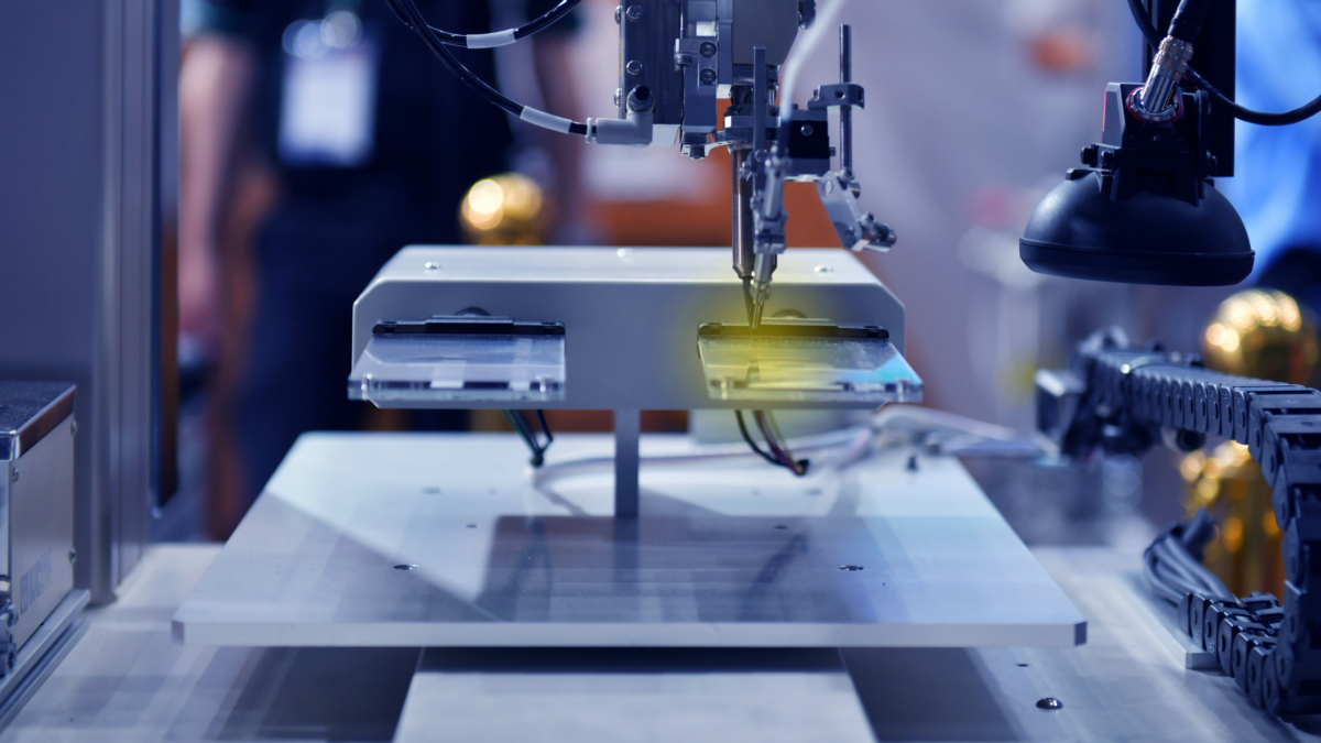
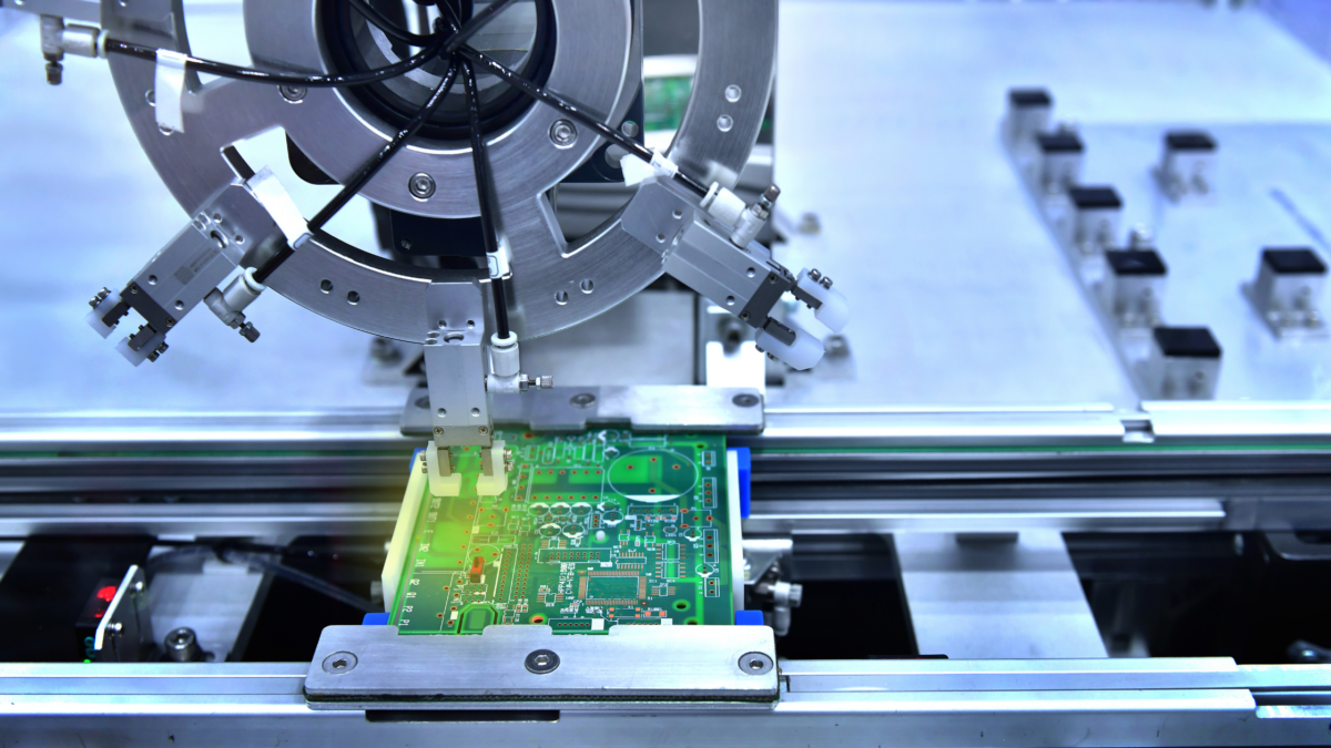
Automation in PCB assembly is no longer a luxury—it’s a necessity. AI-powered automated optical inspection (AOI) and robotic soldering are transforming PCB assembly trends, enabling faster production, fewer errors, and higher efficiency. AI-driven analytics optimize workflows, reducing waste and improving quality control. At Nova, we integrate cutting-edge automation to streamline production, ensuring high-volume orders meet the highest industry standards.

3. Flexible & Wearable Electronics

The growing market for wearable tech and flexible electronics is pushing PCB manufacturers toward flexible and rigid-flex PCBs. These boards, made from polyimide or other bendable substrates, allow for curved and adaptable designs used in medical wearables, smart textiles, and automotive applications. 2025 PCB trends will see increased demand for flex-rigid PCB solutions, and Nova is well-equipped to deliver high-quality flexible circuits that meet durability and performance requirements.

4. Sustainability & Eco-Friendly Materials

As industries shift toward greener practices, sustainability is a critical factor in the future of circuit board assembly. The push for lead-free solder, recyclable PCB materials, and energy-efficient production processes is stronger than ever. Companies investing in sustainable PCB assembly will gain a competitive edge, reducing environmental impact while meeting regulatory standards. Nova is committed to eco-conscious manufacturing, sourcing high-quality, sustainable materials while optimizing processes to minimize waste.

5. Internet of Things (IoT) Integration & Advanced Connectivity

With billions of IoT devices expected by 2025, PCBs must support low-power consumption, wireless communication, and high-speed data transfer. IoT-driven applications require PCBs with multi-layer stack-ups, embedded sensors, and enhanced RF capabilities. Nova specializes in designing and assembling IoT-compatible PCBs, ensuring seamless connectivity and efficiency for smart home devices, industrial automation, and medical monitoring systems.

Looking Ahead: The Evolution of PCB Assembly

The future of circuit board assembly is defined by miniaturization, automation, flexible electronics, sustainability, and IoT-driven designs. To stay competitive, manufacturers must embrace innovation and adapt to the latest PCB assembly trends. At Nova Engineering, we leverage over 35 years of expertise, cutting-edge production lines, and a commitment to quality to help our clients bring their products to life.

Whether you need turnkey assembly, consigned assembly, or a high-volume production partner, we’re here to help. Let’s build the future of electronics—together.

Ready to take your PCB assembly to the next level? Request a quote today!

Top 5 Latest PCB Board Assembly Equipment

The process of assembling a PCB board has become both increasingly precise and technologically advanced. Whether you’re just starting to build a PCB board or you’re working with an established assembly company, the latest PCB board assembly equipment can take efficiency and accuracy to the next level. With each new breakthrough in assembly technology, the process becomes faster and more reliable, providing the foundation for cutting-edge electronics.

Here’s a rundown of the essential equipment needed for PCB board assembly in 2024:

1. Solder Paste Printing Machine

In PCB assembly, applying solder paste is the crucial first step. This paste, often a mix of tin, lead, and silver, acts as an adhesive, allowing components to securely bond to the board. The solder paste printing machine ensures a precise and consistent application of this paste onto the board’s SMD pads through the use of a stainless-steel stencil.

Today’s solder paste printers come equipped with enhanced precision capabilities, driven by AI algorithms that adapt to each board’s layout. These machines minimize waste and guarantee that solder is applied uniformly, which is vital for the success of the entire assembly process.

2. Advanced Glue Dispensing Machine

To avoid component displacement during reflow soldering, glue dots are strategically applied to the board using a glue dispensing machine. With the rapid pace of modern PCB board assembly, this machine is more critical than ever, especially for double-sided boards where components could otherwise fall off due to gravity or the force of the solder wave.

The latest glue dispensers offer adjustable speed and dispensing pressure settings, allowing manufacturers to customize glue application based on component size and layout. These features help avoid glue overflow, which can interfere with soldering and affect the functionality of the finished PCB.

3. High-Efficiency Reflow Soldering Machine

Reflow soldering remains the most widely used soldering method in PCB assembly. This process involves heating the PCB in a reflow soldering oven, where it passes through zones of increasing and decreasing temperatures. The latest reflow soldering machines feature sophisticated thermal profiling, which prevents overheating and ensures a solid bond between each component and the PCB.

Advanced models now use machine learning to monitor temperature zones and predict any potential issues before they arise. This innovation reduces the chance of defective boards and shortens the overall assembly time, which is especially valuable for large-scale PCB production.

4. Automated Optical Inspection (AOI) System

As PCB designs grow in complexity, thorough inspection becomes essential. Automated Optical Inspection (AOI) systems have become indispensable in identifying defects early in the assembly process. Modern AOI systems utilize high-resolution cameras, laser measurements, and AI-driven pattern recognition to detect issues with unmatched accuracy and speed.

The latest AOI systems in 2024 can identify even the subtlest irregularities, such as micro-cracks, tombstoning, and misalignments, which would be impossible to detect with the naked eye. These systems reduce the risk of defects reaching the final product, saving both time and material costs in the long run.

5. Functional Validation Test (FVT) Systems

Once assembly is complete, the Functional Validation Test (FVT) checks that the board performs as intended in its real-world application. Unlike earlier inspection methods, which only focused on physical flaws, FVT involves loading software onto the PCB and testing its performance within the end product environment.

The latest FVT systems offer modular testing capabilities, allowing manufacturers to quickly adapt the test parameters to different PCB designs. This flexibility is particularly beneficial as custom PCBs become more common, enabling tailored testing solutions that match the board’s end-use application.

Crafting Perfection: How Advanced Machines Revolutionize PCB Assembly

As the industry advances, manual soldering and assembly are becoming increasingly rare for large PCB production runs. With innovations in PCB board assembly equipment, companies can now build a PCB board faster and more accurately, minimizing errors and maximizing reliability. For businesses in need of high-volume, high-quality assembly, these cutting-edge machines deliver precision that meets the demands of today’s sophisticated electronics market.

How to Print Circuit Board with PCB Assembly Process

Our daily lives are completely dependent on electronics. Electronic components are present in everything, from our cars to our smartphones. The printed circuit board (PCB), also called the brain of these electronics, is at its core.

The majority of individuals can identify printed circuit boards when they see one. You’ll find these tiny chips covering copper and lines components at the centre of disassembled electronic gadgets. These boards are made of copper, fiberglass, and other metal components. They are joined together by epoxy and solder-masked for insulation, and this solder mask is the source of their distinctive green hue.

Let’s explore the process of printed circuit boards with the PCB Assembly Process.

Step 1: Solder Paste Stenciling

You have to apply solder paste on the board as the initial step in making PCBA. Except for using a mask, this procedure is similar to one used for shirt screen-printing. Consequently, only certain sections of the potential PCB can receive solder paste application from assemblers. The assemblers apply the solder paste where they have to place the components.

Step 2: Pick and Place

With the help of pick and place device, the PCBA process continues. Pick and place device installs mounting components or SMDs on the PCB. If you see a PCB, you will find that most non-connectors are SMDs.

Step 3: Reflow Soldering

After assembling, the assemblers ensure that the components and solder paste stays in place. Therefore, they let the solder paste dry before placing the components. Reflow is a technique used in PCB assembly to achieve this.

Once the pick and place procedure is finished, the PCB board is moved to a conveyor belt. A huge reflow oven—which resembles a commercial pizza oven—passes down this conveyor belt. The board is gradually heated to about 480 degrees Fahrenheit or 250 degrees Celsius in this oven, which is made of several heaters. This temperature will cause the solder in the solder paste to melt.

Step 4: Inspection and Quality Control

It is necessary to test the constructed board for operation once the surface mount components have been soldered during the reflow process. This does not signify that the PCBA has been completed. The movement during reflow frequently causes a connection to be of poor quality or lost entirely. This movement can occasionally result in misplaced components connecting parts of the circuit that shouldn’t be connected, leading to shorts, another frequent adverse effect.

Step 5: Through-Hole Component Insertion

Besides SMDs, there are other components on the board. But, the number of other component depends on the board’s type.The most popular type of PCB process is plated through-hole.

A PCB hole fully plated throughout is known as a plated through-hole.The holes help PCB components to transfer signals to the entire board. It is not possible to use soldering paste on this section of the board because it flows inside the hole without creating a bond between components.

Step 6: Final Inspection and Functional Test

After soldering, you have to conduct a test to check the capabilities of the board. A “functional test” is what is being performed here. This step evaluate the performance of the board while imitating the typical operating conditions. The PCB is exposed to the simulated signals and powerin this test while testers observe electrical properties.

Conclusion

The most effective method for cleaning residue off PCBs is to use a stainless-steel, high-pressure washing machine with deionized water. The gadget is not at risk while washing PCBs in deionized water, so the actual water itself—rather than the ions it contains—causes harm to a circuit. As a result, PCBs can be washed in deionized water without harm.

Comparison Between Standard PCB and Metal Core PCB

Metal-core printed circuit boards have increased in popularity alongside the popularity of LED-based products during the past few years. Given that an LED-based light can be around 5 times more cost-effective to operate than a comparable incandescent unit, the automotive and lighting industries have welcomed the technology, as have consumers. Even smaller fluorescents have slightly higher operating costs, and when it comes to making the best use of available space, they fall short of the smallest LEDs.

These and other reasons have led to an increase in the number of gadgets that use LEDs as a key component of their design. However, heat is one component of LED functioning that must always be considered when designing products.

Standard PCB

We are a full-service supplier of both standard and unique printed circuit boards. A standard printed circuit board is the most popular PCB solution for every need. We can offer quick turn times and flexibility to meet our customers’ strict project deadlines thanks to our U.S.-based manufacturing facilities and the most modern PCB fabrication equipment.

There are various common or standard PCB thicknesses available for PCBs. 0.062 inches, 0.093 inches, and 0.031 inches are a few of them. Naturally, various design and manufacturing aspects should be considered when establishing the PCB thickness.

Once the prototype boards have been created and your idea has been thoroughly evaluated, standard PCBs are useful. After that, ordering standard PCBs in quantity can significantly reduce expenses. Strict internal quality assurance testing can be used to ensure that standard PCBs are completely dependable and comply with IPC 2.

After the prototype and design phases are complete, standard PCBs are widely used in high-volume production runs. They function effectively even for enormous designs since they can largely print sophisticated circuit boards. All standard PCBs have had their designs for manufacturing analyzed, ensuring that the PCB design will function as intended.

The only need to use this particular board size is if you are designing to some standard, although many fabrication firms will probably advertise their capacity to make 1.57 mm boards. Instead of 1.57 mm thick boards, standardized interfaces like Mini PCIe use 1 mm thick.

Metal Core PCB

LEDs are similar to other circuit board-mounted components in many aspects. There isn’t much of a purpose to interestingly arranging your PCB if there are only a few LEDs, such as green and red power-on and power-off indicators. There are other lighting options, though, that use rows or arrays of LEDs that are continuously on.

Keeping these devices cool is important to prevent early failure or the creation of a safety concern. Additionally, efficient cooling is necessary to ensure constant light output.

Using unique substrate materials that are specially prepared to increase the reliability of designs that operate at higher-than-usual temperatures is one advantage of a metal core PCB. The substrate actively transfers heat from hot-running component locations to the layer on the opposite side of the board, where it can be safely and effectively dissipated instead of only acting as a mounting platform for the various components.

Conclusion

The final decision will depend on your specific application requirements. Metal core and standard printed circuit boards have several differences, and standard boards work perfectly if you want to maintain flexibility with PCB thickness. However, metal PCBs would be preferable for electromagnetic shielding and minimizing board space.

A solid-state relay architecture requires a thermally efficient and mechanically durable structure, which metal core PCBs offer. To satisfy the demands of excellent thermal performance that can even outperform current ceramic-based designs, manufacturers are finding new forms of metal core PCB material, especially dielectrics.

Why is Metal Core PCB Important?

Metal Core PCB are composed from copper film used for circuit lithography, a metal layer with a high heat dissipation capacity, and a dielectric layer. Copper and aluminiumare the materials most frequently used to fabricate metal layers. However, manufacturers also use stainless steel sometimes. Copper outperforms aluminium in terms of performance and electrical characteristics, but copper is more expensive.

The metal layer can be 100% metal or partly fibreglass (FR-4). Due to its high manufacturing complexity, the multilayer version of metallic PCBs is less prevalent. Instead, they can be single or double-sided. A multilayer MCPCB requires that the layers be distributed equally concerning the inner metal layer; for instance, a PCB with 12 layers would place the metal layer in the middle of the stack-up, with 6 layers above and 6 layers below.

Benefits of Metal Core PCB

Metal PCBs provide superior capacitive coupling, strong electromagnetic shielding, increased power density, and efficient thermal dissipation. Thermal vias, which are used in conventional PCBs, can further enhance thermal performance. Here are the top benefits of Metal Core PCB:

  • Thermal Dissipation

One PCB alternative with a higher heat conductivity is metal core PCB. They avoid potential circuit damage, increase power levels, and manage high-density circuits by keeping the heat as far away from the power components as feasible. Aluminium is a popular material for metal core PCB because it is affordable, recyclable, and has good electrical qualities. Moreover, metal core PCBs are incredibly faster than standard PCB.

The dielectric layer should be thin to establish the simplest path with the metal plate, and it typically has a thickness of about 0.003 to 0.006 inches. For instance, a test on a metal core PCB using integrated 1W LED revealed that its temperature stayed very near 25°C. However, the same power LED installed on a PCB attained a temperature 12°C higher than 25°C.

  • Better Stability and Strength

The rapid LED technology’s growth has highlighted concerns about heat dissipation. Particularly high-power LED lights and the circuit may have reliability and stability issues because these LEDs are typically positioned directly on the PCB. Heat dissipation can impair the operation of electronics that use a lot of power if the proper technique is not used. 

This issue is successfully resolved using metal PCBs. Aluminum adds resistance and strength to the PCB without adding weight and ensures longevity.

  • Dimensional Stability

As external circumstances change, metal core PCB’s size will remain more stable than one made of more conventional material, such as FR-4. PCBs containing metal layers have had a relatively slight size variation, between 2.5% and 3.0% when heated between 30°C to 150°C.

  • Longer Lifetime

Aluminium offers superior strength and longevity compared to materials such as fiberglass and ceramic, frequently used in producing PCBs. It consist of strong metal and reduces the risk of breakage during different production phases, while using finished products or assembly.

Conclusion

In contrast to ceramic substrates, the material architecture of metal core PCBs enables mounting configurations appropriate for solid-state relays in various control applications. A solid-state relay architecture requires a mechanically durable structure and thermally efficient, which metal core PCBs provide. 

Manufacturers are developing new forms of metal core PCB material, particularly dielectrics to achieve high thermal performance requirements that can even outperform current ceramic-based designs.

How Do You Define a PCB?

This post will talk about one thing only: Printed Circuit Boards, or PCBs for short. You must know that the world of technology keeps expanding as new devices, gadgets, and equipment make their way into our lives. What keeps the electrical appliances and equipment running? Is there a core component without which your electrical device, like a smartphone, laptop, or vacuum cleaner, won’t work? Yes!

Printed Circuit Boards are the core components of many electrical devices. In technical terms, a PCB creates conductive pathways to connect and mechanically support electrical components. We won’t be talking in purely scientific and mathematical lingo – don’t worry! Let’s find out what a PCB refers to and what it does.

What Do You Define a PCB in Technical Terms?

Here’s how you define a Printed Circuit Board or PCB:

“A PCB forms the board base for connecting and supporting multiple electrical components using the surface mount technology to run electronic products.”

Have you ever accidentally cracked open your phone or even an electronic toy? Did you see a green electric board with numerous wires attached to different parts of the individual item? Well, that’s a PCB! It has socketed or open components that transfer electrical signals and conductive traces through conductive pathways to run an electronic product.

Like animal and plant cells require a nucleus at the center to function and coordinate other mechanisms, nearly every electronic product requires circuit boards. A more technical term for circuit boards is “printed circuit boards”. Many standard devices like laptops, smartphones, and even vacuum cleaners won’t work without it.

How Do Factories Make PCBs?

PCBs are electrical circuit boards in various shapes, sizes, and designs. Since they fit many electronic product categories, they are not the same. Factories are the production houses where electrical circuit boards get fused with electrical components to produce PCBs!

Every PCB is different yet vital to the functionality of the device it’s for. The most standard version is a plastic board covered with fiberglass. Having a non-conductive plastic board is essential to make a high-quality board. The manufacturers create small conductive pathways on that board to mount and connect multiple electrical components.

The conductive traces (pathways) assist components in passing electric signals through it. It contains numerous holes to fit each component. First, manufacturers add a soldering paste to the board, passing it through the “pick and place” technique where components are attached to it.

Second, it goes through the soldering process to permanently attach every component to the board. Then, the board goes through physical and functional inspection (testing phase) to ensure high-quality production. Finally, the factories receive test feedback and performance reports before readying them for supply to the market. 

What Happens When a PCB Corrupts or Malfunctions in a Device?

Printed Circuit Boards are the core components of electronic devices. So, when the board takes out or if it malfunctions, the device will probably stop functioning. Even if a single important component malfunctions on the board, the whole device could malfunction or stop working altogether.

Fixing it as soon as it gets damaged or malfunctions is the best approach, especially when it’s an essential household or personal device like a smartphone or laptop. There could be dozens of issues and reasons behind a PCB not functioning correctly, including:

  • Poor soldering
  • Low-quality soldering paste
  • Damage in the assembling process
  • Heat-up issues
  • Poor-quality components 

Conclusion

You will only have a limited range of electronic products if factories stop producing electrical products, mainly printed circuit boards. You can only imagine how far the effect of PCBs travels in our daily lives. PCBs are in numerous devices, from personal hygiene products to military equipment and navigational systems.

What are the Most Important Components of a PCB?

Printed Circuit Boards feature the Surface Mount Technology these days. Therefore, components of a PCB tend to be a lot on a single board; sometimes, up to a hundred components at once! It’s worth knowing that PCBs or printed circuit boards are the core components of our essential electronic devices and equipment. Without PCBs, your phone won’t work.

While learning about PCBs, most readers find one topic very interesting. That topic relates to the different components that make up a PCB. In surface mount boards, dozens of electrical components are connected via conductive pathways. Let’s learn about some of those components below.

7 Most Important Components of a Printed Circuit Board (PCB)

PCBs contain a wide range of electrical components that perform different functions based on the host device. They’re vital for the functionality of a device like a laptop, washing machine, or calculator. The number and type of components can vary significantly based on the device and PCB type. However, the most common types of electrical components infused in a printed circuit board include:

  • Resistors
  • Transistors
  • Inductors
  • Capacitors
  • Transformers
  • Sensors
  • Diodes

If even one component stops working, the whole PCB shuts down. Thus, the device it belongs to will shut down as well. Here, we will discuss the crucial PCB components, what they do, and why they’re important.

  • Resistors

They’re among the most crucial components in nearly all types of printed circuit boards. They produce and transmit electric currents to cause a voltage that helps dissipate electric power as heat energy. Although resistors have the same purpose, they still come in a wide variety in terms of shape, size, and power. They’re basically based on the resistance value and are easy to identify using color codes.

  • Transistors

Think of a transistor as an amplifier that switches and regulates electronic signals in a printed circuit board. These electrical components also come in a wide variety, but the most typical transistor in use is the “bipolar transistor”. It has three pins that form (i) the base, (ii) the emitter, and (iii) the collector. 

  • Inductors

Inductors are quite similar to capacitors in printed circuit boards. They store a specific energy quantity in the form of magnetic fields right when an electric current passes through them. Their main purpose is to block electric signals in the board to prevent interference that could occur due to a connection with another electronic device or equipment. 

  • Capacitors

These electrical components are quite famous in the electronics world. These hold an electric charge in the board and release it through the PCB whenever different parts of the board require power. It collects opposite charges on separate conductive layers using an insulating material.

  • Transformers

Transformers are essential components that form high-quality PCBs. With a transformer, electrical energy flows from one circuit board to another along with correct voltage fluctuations to suit the transfer. 

  • Sensors

Sensors detect environmental and other external factors (in numerical values) and release an electric current (as a signal) in the circuit board. The electrical signal they generate corresponds with the circuit board and associated components to cause an effect or change. Sensors detect physical elements and external factors such as air quality, sound, and light motion and convert them into electrical signals.

  • Diodes

Diodes prevent electrical current from flowing in the wrong direction inside the conductive pathways of a printed circuit board. It blocks the electric current from going in the wrong direction to prevent excessive damage to the circuit board. The most popular diode is the LED or “Light-Emitting Diode”. 

Conclusion

What happens when a single component malfunctions in a printed circuit board? The whole PCB can malfunction and shut down the device it’s in! If it’s your smartphone or laptop, you’ve got little or no time left to use it if the PCB’s damaged (i.e., motherboard). That’s why manufacturers only source high-quality PCB electrical components to ensure the circuit boards function as intended.

The Right Way to Solder on Printed Circuit Boards

Soldering is the most vital part of the PCB assembly process. It’s where the electrical components get attached to circuit boards. Without electrical components, no PCB would function effectively. There are various methods to sell electrical components to PCB and ensure electrical currents pass through the conductive pathways efficiently.

The main issue is that many people don’t know the right way to solder electrical components on circuit boards. Since a bunch of them are being used in factories, it can be quite tricky to pick the right one. We will discuss some of the top soldering techniques so you can choose the one that’s right for your business.

The Right Way of Soldering on Printed Circuit Boards

In the electronics world, soldering is a fundamental skill that nearly every professional must have at some point. Soldering and electronics go together like a fork and spoon.

Although people learn how to design, build, and release electronics without picking up a soldering iron, it’s still a vital part of the industry. Let’s check out a few soldering methods and techniques commonly used these days.

1.      Reflow Soldering

It’s the most common soldering method factories use today, especially for manufacturing surface mount technology or SMT printed circuit boards. This soldering method involves using a heated soldering paste to attach electrical components to the circuit board. The paste looks like molten metal, enabling professionals to connect pins and pads seamlessly. However, it results in permanent attachment.

2.      Wave Soldering

Wave soldering was once extremely popular for wave soldering. However, it’s still commonly used for surface-mount technology circuit boards. Printed circuit boards that go through the through-hole process (i.e., drilling holes in the board to fit electrical components) usually also go through the wave soldering process.

Generally, factories utilize wave soldering to produce massive PCB assemblies. The PCBs go over molten solder in a pan that looks nothing less than a wave pool. Once through, electrical components get attached to the circuit board.

Before coming in contact with the molten solder, the components are already glued to the board. Due to an additional step that reduces efficiency and somewhat increases the time and money consumption, reflow soldering replaced wave soldering.

3.      Braze Soldering

Soft and hard soldering is nothing compared to brazing. Brazing results in fortified joints between the printed circuit boards and electrical components, including transistors, inductors, and capacitors. It uses high temperatures to attach electrical components to circuit boards.

Although it’s similar to hard soldering (discussed later), brazing involves melting the underside of the metal components to get attached to the board. It causes the least thermal deformation and is one of the best soldering techniques for mass PCB production.

4.      Soft Soldering

Soft soldering is the perfect option for compact and fragile circuit board components. Soft soldering doesn’t damage the electrical components through high heat or molten solder. In this process, the temperature of the molten solder is below 400 degrees Celsius or 752 degrees Fahrenheit.

If the temperature goes over, it becomes “braze soldering”. The low-temperature technique is for smaller components prone to breaking at high temperatures or heat conditions. Although it’s suitable for small components and fragile boards, it doesn’t produce the strongest joints.

5.      Silver Soldering (or Hard Soldering)

This soldering technique also yields strong joints between components and circuit boards. However, combining metal components such as gold, silver, or brass-plated components is best. It’s used to connect and attach the same metals in other industries.

Conclusion

What type of printed circuit board you’re producing will determine the right soldering technique. Other factors influencing the soldering technique include existing capabilities, materials, and requirements.

Check which soldering technique offers the most lasting results and try to match it with your PCB requirements. Partnering with a solid PCB manufacturing company could ease the process and increase soldering efficiency.

The Key Characteristics of the Surface Mount Technology: PCB Assembly

Surface Mount Technology or an SMT is a method of manufacturing circuit boards. The alternative to this would be through-hole circuit boards with different circuit board designs. Most circuit boards that you see in mobile phones today are a bunch of small chips placed on top of a circuit board panel.

Surface Mount Technology

A circuit board with surface mount technology will not necessarily have holes inside. Instead, they are on top of copper pads and copper traces on the circuit board. This surface mount technology is a semi-automated process that allows manufacturers to build all the different circuit boards in-house for various products.

With the help of this technology, manufacturers can easily mount electronic components on the surface of printed circuit boards. This mounting technique is very different from the insertion technique that manufacturers conventionally use with holes.

In other words, it is an alternative to the older practices of developing circuit boards with the help of through holes. Since it is a newer rendition, it overcomes many shortcomings of the through-hole technology on the surface mount.

SMD

One of the critical characteristics of the surface mount technology is an SMD, otherwise called a surface mount device. When you browse the markets, you will find multiple range packages of SMD. These packages vary in different sizes and shapes.

SMD Passive Components

A large portion of the SMD resistors are either capacitors or resistors. The package sizes of these passive components come in sizes standard pack. Other surface mount device components include crystals and coils.

Resistors and capacitors generally vary in dimensions, shapes, and sizes. Other forms of SMD components that you can find include diodes and transistors. These are often very small in regards to shape and size. They connect within a circuit board with the help of leads.

Approximately three leads are included within these packages. Identifying which way the device must shift can help with the manufacture of the printed circuit board.

Integrated Circuits

You will find that there is a variety of packages that come in handy for integrated circuits. The use of the package depends entirely on the amount of interconnectivity that the component needs. For instance, a logic chip is only installed with 14 to 16 pins. On the other hand, other processors and chips can come with about 200 or more.

Since requirements can vary so greatly, there are a number of different packages that you can find. Like the packages, the processes in the SMT process also differ from the conventional through-hole PCB method.

Solder Paste Printing

One of the most distinctive processes of the SMT method involves solder paste printing. This refers to the place where you need components. The printed circuit board usually comes with a very fine and thin piece of metal.

On the circuit board, there are solder pads. In surface-mount technology, stencils and squeegees usually do the job of applying solder to the appropriate pads on the circuit board. This method of solder mask application is becoming very widely used and popular. This is especially the case in the subcontract sector.

To Conclude

As you can see, the surface mount technology has great significance today and is prevailing against the conventional through-hole method. The characteristics of the surface mount technology in the PCB manufacturing industry, along with its large-scale implementation are speeding up the manufacture of electrical appliances and technology. This, in turn is accelerating the world towards a prosperous future.