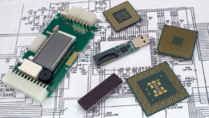
Advancements in Materials – Explore Latest in PCB Substrates

While traditional materials have served as the backbone of PCBs, a closer examination reveals inherent limitations and challenges. Understanding these constraints sets the stage for exploring cutting-edge solutions. The heart of innovation lies in printed circuit boards (PCBs) for the electronics industry. Within this dynamic industry, the substrates that underpin PCBs have emerged as a focal point of exploration and advancement. PCB substrates have moved from the foundations of traditional materials to the noncomposite wonders. By discussing how these advancements are reshaping industries and propelling us into an era of unprecedented electronic possibilities, we will know how to take leverage of this advancement.

What Are PCB Substrates?

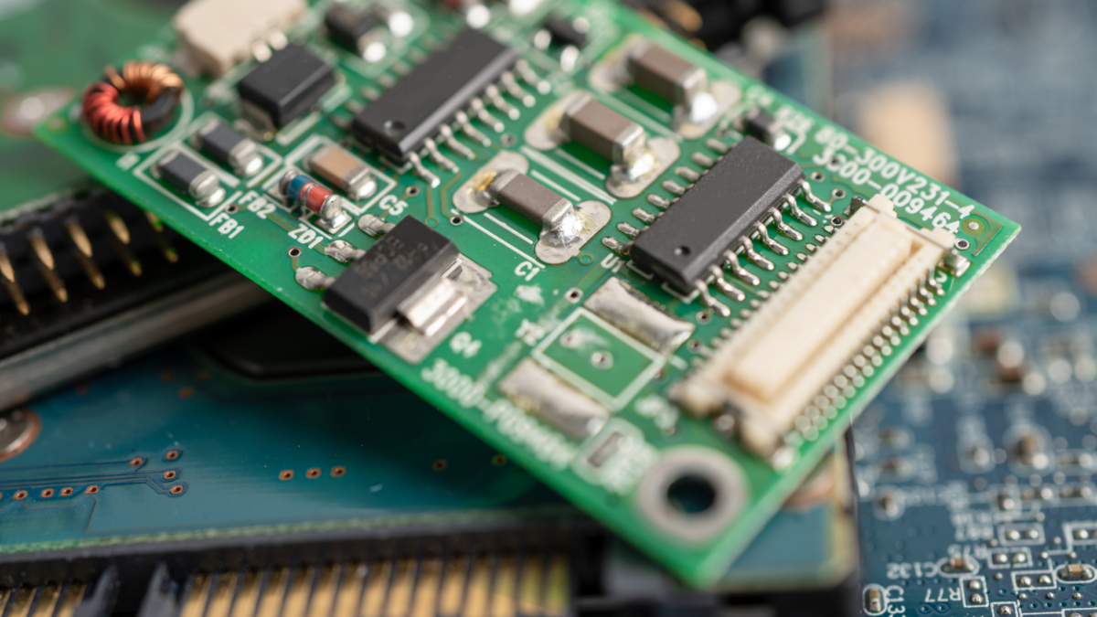
Printed Circuit Board (PCB) substrates are the foundational materials that provide mechanical support and electrical insulation for the components on a PCB. These substrates serve as the base upon which the conductive paths and electronic components are mounted. Typically composed of insulating materials, PCB substrates play a crucial role in supporting the conductive traces that facilitate the flow of electrical signals throughout the circuit.

The choice of substrate material is vital, influencing the board’s performance, reliability, and overall functionality. Common materials used for PCB substrates include fiberglass-reinforced epoxy laminates (FR-4), which are widely employed in conventional PCBs, and more advanced materials like flexible polymers or ceramics for applications requiring flexibility or high-frequency performance.

Latest Innovations in PCB Substrates

PCB substrates provide a platform for the intricate interconnection of electronic components, enabling the creation of complex circuits that power a diverse array of electronic devices, from smartphones to industrial machinery. The continual innovation in PCB substrate materials contributes to the ongoing evolution of electronic technology, allowing for improvements in performance, miniaturization, and the development of new functionalities.

High-Frequency Materials

High-frequency materials represent a significant stride in the evolution of PCB substrates, particularly in response to the demands of new tech such as 5G communication. These materials exhibit low signal loss and enhanced signal integrity, crucial for transmitting data at higher frequencies. Common high-frequency substrate materials include polytetrafluoroethylene (PTFE) and ceramic-filled hydrocarbons. Adopting these materials enables the design of PCBs capable of supporting the rapid data rates required for next-generation wireless communication and other high-frequency applications.

Flexible and Rigid-Flex Substrates

The advent of flexible and rigid-flex substrates marks a departure from the rigid confines of traditional PCBs. Flexible substrates, often composed of polyimide, allow PCBs to bend or conform to non-planar surfaces, opening up new possibilities for wearable devices and unconventional form factors. Rigid-flex substrates combine flexible and rigid materials in a single board, balancing adaptability and structural integrity. This innovation is reshaping the design landscape, enabling the creation of foldable smartphones, flexible displays, and other compact electronic devices.

Nanocomposite Materials

Nanocomposite materials revolutionize PCB substrates by incorporating nanoparticles into the base material. These nanoparticles, often carbon-based, enhance mechanical strength, thermal conductivity, and electrical properties. The resulting PCBs exhibit improved performance, reduced size, and increased reliability. Nanocomposites are especially valuable in applications where size and weight are key factors, such as aerospace and medical devices. As technology advances, integrating nanocomposite materials into PCB substrates propels electronic devices into realms of previously unimaginable efficiency and capability.

Final Thoughts

Exploring the latest innovations in PCB substrates reveals a tapestry of technological breakthroughs poised to redefine electronic devices’ capabilities and design possibilities. The convergence of high-frequency precision, flexible adaptability, and microscopic enhancements of nanocomposite materials underscores the dynamic nature of electronic engineering. It sets the stage for a future where devices are interconnected and optimized for efficiency, performance, and versatility.

As we stand on the brink of this transformative era, the journey through these innovations in PCB substrates signals progress and a profound leap forward into the next generation of electronic design and functionality.
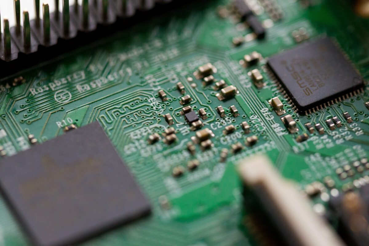
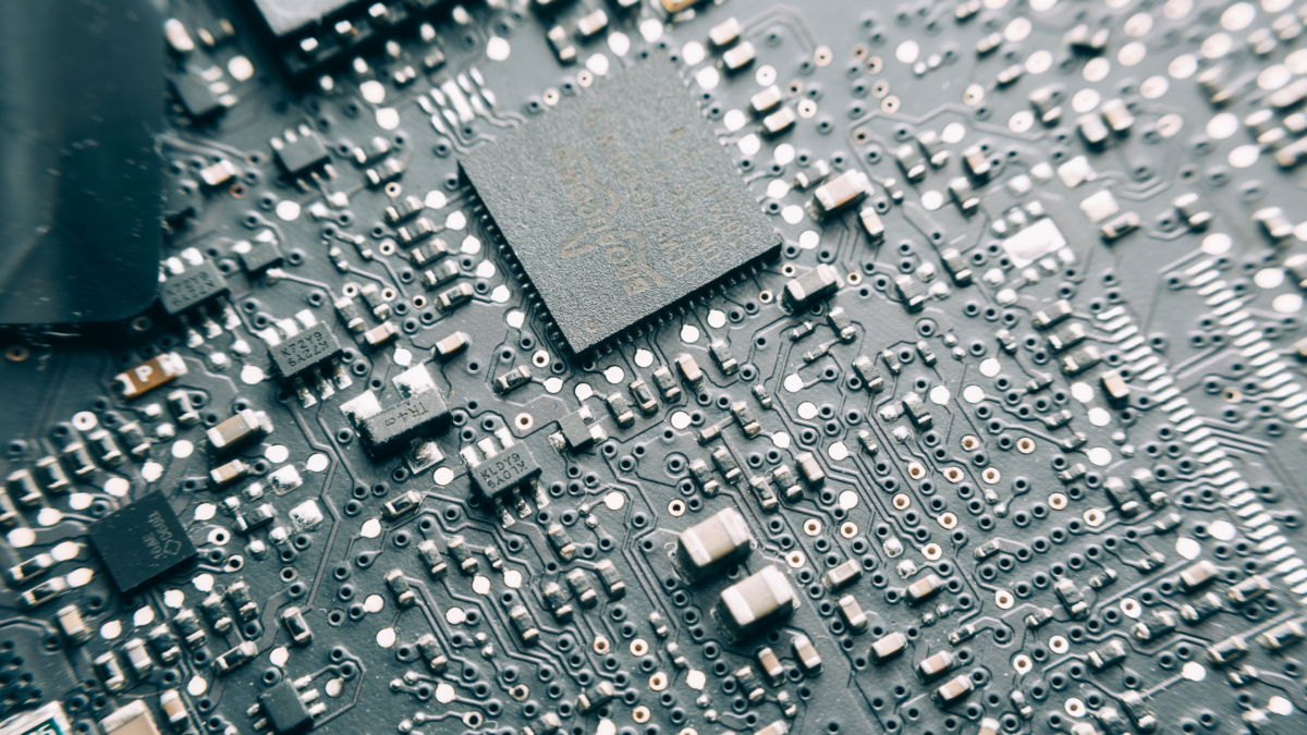
A Beginner’s Guide to Circuit Board Assembly

You may not realize it, but printed circuit boards are more important and common than you think. Present within a vast majority of the electronic devices we use daily, these circuit boards are a vital component that ensures the proper functionality of electronics.

Keeping this in mind, it is essential to understand that the assembly of these circuit boards is vital, primarily because they are a major component within electronics.

Because of the components and circuitry involved within an average PCB, the manufacturing process is incredibly complex.

Not only that, but the board you are working on also needs to be reliable enough to support the assembly process so that the resulting PCB does not turn out to be faulty.

Let us discuss this in further detail, exploring deeper into the concept of PCB assembly, understanding the resources needed, and the assembly process itself.

PCB Assembly: In Depth

Before going into the specifics of the overall process, let us first establish a foundation: the assembly process, taking a broader look at this part of PCB development.

Simply speaking, the initial state of a circuit board that has yet to go through any component installation is a printed circuit board, also known as the PCB.

When the necessary electrical components have been installed onto the board, the resulting circuit board that we end up with is called the printed circuit board assembly, otherwise known as a PCBA.

Many people consider the PCB assembly and manufacturing process as the same thing, but that is not the case.

The main reason why assembling the circuit board is different is that when the PCB is being manufactured, it goes through a selection of different catering to the design and creation of the board.

However, assembly is what comes after the board has been developed after going through the design phase, involving the assembly of the electronic parts according to the main function of the PCB.

Resources Needed for PCB Assembly

Some certain tools and components are required to ensure that the overall assembling of the PCOB goes smoothly, and these include:

  • The printed circuit board itself
  • Transistors and other basic electronic components
  • A soldering flux
  • Necessary tools to perform a solder, including a soldering wire, soldering iron, and testing equipment.

Different Techniques of PCB Assembly

Even though the through-hole insertion technique for applying electrical components was the only way to develop PCBs, technological advancements have led to other methods, such as assembling a circuit board through SMT.

Assembling Using Thru-Hole Components

This type of PCB assembly involves certain components with wiring coming out of them, which go through the tiny holes within the PCB and are soldered.

When assembling a PCB using thru-hole components, it goes through a process called wave soldering, which involves the being applied in the form of a solder bar, which is put in an incredibly hot bath. This high temperature makes the solder stay molten and creates a wave-like design.

Once the wave has been made, the electrical components are passed through the molten state to be fitted within their places.

The overall assembling and solder process for these components includes:

  • Insertion of the necessary electronics
  • Applying the solder flux
  • Preheating the solder bar
  • Creating the wave solder
  • Cleaning and inspecting the PCBA
  • Testing the final product

Assembly Using SMT

Also known as surface mounting technology, this assembly process involves special components that do not contain any leads and do not need to go through any holes to be soldered.

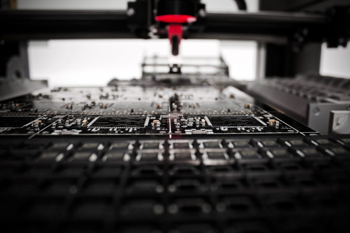
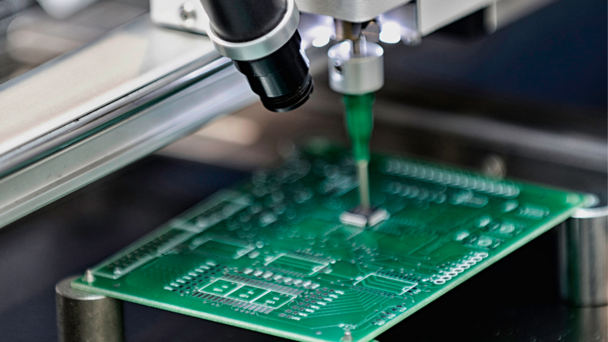
Using this technology, they are directly soldered onto the PCB and are highly compatible with automation, leading to machinery automating the entire assembly process.

Conclusion

Many factors need to be considered when assembling a printed circuit board. However, with the right tools and components, you will not face any problems if you follow the steps mentioned above to assemble a PCB.

RoHS Compliance and Lead-Free Soldering Techniques

One of the significant steps towards achieving environmental responsibility was the introduction of RoHS compliance regulations. RoHS, which stands for Restriction of Hazardous Substances, is a directive aimed at reducing the use of hazardous materials in electrical and electronic equipment. This directive has driven the adoption of lead-free soldering techniques in electronics manufacturing. In this article, we will explore RoHS compliance, its significance, and the lead-free soldering methods that have become central to it.

RoHS Compliance: A Brief Overview

The RoHS directive, formally known as Directive 2011/65/EU, originated in the European Union but has had a global impact on the electronics industry. Its primary objective is to restrict the use of specific hazardous substances in electronic and electrical equipment. These substances include:

  • Lead (Pb)
  • Mercury (Hg)
  • Cadmium (Cd)
  • Polybrominated biphenyls (PBB)
  • Hexavalent chromium (Cr6+)
  • Polybrominated diphenyl ethers (PBDE)

The RoHS directive applies to a wide range of electronic products, from household appliances to industrial machinery. Manufacturers and suppliers must comply with RoHS regulations to market their products in the EU and other regions that have adopted similar standards.

The Significance of RoHS Compliance

RoHS compliance carries several significant advantages and benefits, both for the environment and for consumers:

  • Environmental Impact

By restricting hazardous substances, RoHS helps reduce the environmental footprint of electronics manufacturing. It limits the release of toxic materials into the environment, thereby mitigating potential harm to ecosystems and human health.

  • Product Safety

RoHS compliance ensures that electronic products are safer for consumers. It reduces the risk of exposure to hazardous substances, particularly in consumer electronics and appliances that may come into direct contact with people.

  • Recycling and Disposal

RoHS-compliant products are easier to recycle and dispose of responsibly. They contain fewer hazardous materials, making them safer for recycling and preventing the contamination of landfills.

  • Global Market Access

Compliance with RoHS regulations enables manufacturers to access global markets. Many countries and regions outside the EU have adopted similar standards, making RoHS compliance essential for international trade.

Lead-Free Soldering Techniques

One of the most significant changes driven by RoHS compliance is the shift from lead-based solder to lead-free solder in electronics manufacturing. Lead-free soldering techniques have become central to achieving RoHS compliance. Here are key aspects of lead-free soldering:

1. Composition

Lead-free solder alloys are typically composed of various metals, with tin (Sn) being the primary component. Common alloys include Sn-Ag-Cu (SAC), Sn-Cu, and Sn-Ag. These alloys offer comparable or even superior mechanical and electrical properties to traditional lead-based solder.

2. Soldering Temperature

Lead-free soldering often requires higher temperatures than lead-based soldering. This can necessitate adjustments in soldering equipment, such as reflow ovens and soldering irons, to accommodate the higher melting points of lead-free alloys.

3. Compatibility

When transitioning to lead-free soldering, it’s essential to ensure that all components and materials used in the assembly process are compatible with lead-free solder. Some components may require adjustments or alternative materials.

4. Solder Paste and Flux

Lead-free solder paste and flux materials are formulated to work with lead-free solder alloys. These materials play a crucial role in ensuring proper wetting and bonding during the soldering process.

5. Process Control

Control over the soldering process is vital to achieve consistent and reliable solder joints. Manufacturers must fine-tune their soldering profiles to account for the characteristics of lead-free solder, ensuring proper reflow and minimizing defects.

Benefits of Lead-Free Soldering

The adoption of lead-free soldering techniques offers several benefits beyond RoHS compliance:

  • Environmental Responsibility

Lead-free solder reduces the environmental impact of electronics manufacturing by eliminating a highly toxic substance.

  • Health and Safety

Lead-free solder is safer for both manufacturing personnel and end-users, reducing the risk of lead exposure.

  • Recycling

Lead-free solder makes recycling and disposal of electronic products more environmentally friendly.

  • Global Market Access

Lead-free soldering techniques enable manufacturers to access global markets, ensuring their products comply with various environmental regulations.

  • Mechanical Strength

Lead-free solder alloys often exhibit improved mechanical strength, enhancing the reliability of soldered joints.

Conclusion

RoHS compliance and the adoption of lead-free soldering techniques have transformed the electronics manufacturing industry, promoting environmental responsibility, product safety, and global market access. While the transition to lead-free soldering presents challenges, the long-term benefits in terms of sustainability and safety make it a crucial step towards a more responsible and sustainable electronics industry. As technology continues to advance, ongoing research and development will further enhance lead-free soldering techniques, making them even more efficient and eco-friendly.

Surface Mount Technology: What It Means for Modern PCB Assembly

Surface mount technology has become one of the most important methods used in modern printed circuit board assembly. Instead of inserting component leads through drilled holes, this process allows electronic components to be placed directly onto the surface of a PCB and soldered in place. This helps manufacturers build smaller, lighter, and more efficient boards for today’s electronics.

For companies like Nova Engineering, this process supports the precision, speed, and flexibility required for both prototype and production PCB assembly. Nova offers surface mount and mixed technology, helping customers bring reliable electronic products from concept to completion.

What Is Surface Mount Technology?

Surface mount technology, often called SMT, is a process that uses surface mount devices, or SMDs. These components are designed to sit on solder pads on the board rather than pass through holes like traditional through-hole components.

This difference matters because electronic products continue to become smaller, faster, and more advanced. SMT makes it possible to place many components in a compact space while still supporting strong electrical performance. It is commonly used in consumer electronics, medical devices, telecommunications equipment, industrial systems, and other applications where reliability and space efficiency matter.

How the SMT Assembly Process Works

The surface mount technology process is highly precise and typically uses automated equipment. While each project can vary depending on board design and production requirements, the basic process usually includes:

  1. Solder paste is applied to the PCB using a stencil.
  2. Automated pick-and-place equipment positions components on the board.
  3. The board passes through a reflow oven, where solder melts and forms connections.
  4. The finished assembly is inspected for placement accuracy, solder quality, and defects.

Inspection is especially important because SMT components are often very small. Nova uses automated optical inspection, along with detailed quality checks, to help confirm that assemblies meet performance expectations.

Why SMT Is So Widely Used

One of the biggest advantages of surface mount technology is efficiency. Because the process can be automated, it supports faster assemblies and more consistent placement than many manual methods. This is useful for higher-volume production, but it also helps improve repeatability for smaller runs and prototypes.

Another advantage is board density. SMT allows components to be placed closer together, and in many designs, parts can be mounted on both sides of the PCB. That gives engineers more flexibility when designing compact electronics.

SMT can also reduce weight. Since surface mount components are generally smaller than through-hole components, the finished board can be lighter and better suited for portable or space-conscious products.

SMT vs. Through-Hole Assembly

Although SMT is common, through-hole assembly still has an important place in PCB manufacturing. Through-hole components are inserted through drilled holes and soldered on the opposite side of the board. This can provide stronger mechanical connections, which may be useful for connectors, switches, or components that experience physical stress.

Many modern boards use a combination of both methods. This is known as mixed technology assembly. Nova supports surface mount and mixed technology, which allows customers to use the best assembly method for each component and application.

Important Considerations for SMT Components

While surface mount technology offers many benefits, it also requires careful planning. Component size, pad layout, solder paste application, heat exposure, and inspection standards all affect the final assembly.

Smaller parts can improve board density, but they also demand tighter process control. Poor placement, insufficient solder, excess solder, or misaligned components can lead to performance issues. That is why experienced assembly, accurate equipment, and reliable inspection systems are so important.

Why Precision Matters 

A well-built PCB depends on more than the technology used. It depends on how carefully that technology is applied. With surface mount technology, even a small placement error can affect the function of the entire board.

Nova Engineering brings decades of experience to prototype and production PCB assembly. For industries that depend on accurate, reliable electronics, quality assembly is essential. Every board must be built with the right process, the right inspection steps, and the right attention to detail.

Building Better Boards 

Surface mount technology has changed how modern circuit boards are designed and assembled. It supports smaller products, faster production, higher component density, and reliable performance when handled with the right process controls.

For businesses that need dependable PCB assembly, SMT is not just a manufacturing method. It is a practical way to support the advanced electronics people rely on every day.

How Components on a Circuit Board Work Together to Power Modern Electronics

Have you ever thought about how much we rely on electronics every single day? From smartphones to industrial equipment, nearly everything we use depends on components on a circuit board working together seamlessly. Without these carefully designed systems, even the simplest device would not function.

At the core of modern electronics is the printed circuit board, often referred to as a PCB. It is not just a flat surface with parts attached. It is a precisely engineered platform where components interact to control power, process signals, and keep devices running efficiently. Understanding how these components work together helps highlight why quality PCB assembly matters, especially for companies like Nova Engineering that focus on reliability and precision.

Why Each Component Matters

Every PCB is designed with a purpose, and each element plays a specific role. When one piece fails, it can affect the performance of the entire system. That is why properly selected and assembled components on a circuit board are critical for long-term functionality.

Let’s break down some of the most important components and how they contribute to a working circuit.

Resistors: Controlling Electrical Flow

Resistors are one of the most common components on a circuit board. Their job is simple but essential. They regulate the flow of electrical current and help maintain safe voltage levels across the system.

Without resistors, circuits could easily overload, leading to overheating or permanent damage. They ensure that each part of the board receives the correct amount of power, which is especially important in sensitive electronics.

Capacitors: Storing and Releasing Energy

Capacitors act like temporary energy storage units. Among the key components, they store electrical energy and release it when needed.

They help stabilize voltage, filter noise, and support consistent performance. You will find capacitors in almost every electronic device, from consumer products to complex industrial systems.

Inductors: Managing Current and Magnetic Energy

Inductors are another type of passive component that plays a key role in managing electrical flow. These components on a circuit board store energy in a magnetic field when current passes through them.

They are commonly used in power supplies and filtering applications. Inductors help smooth out fluctuations in current and work closely with capacitors to maintain steady operation in circuits.

Transistors: Switching and Amplifying Signals

Transistors are among the most critical components on a circuit board because they act as both switches and amplifiers. They control the flow of electrical signals and allow circuits to perform complex tasks.

There are two primary types used in modern electronics:

  • Field Effect Transistors (FET)
  • Bipolar Junction Transistors (BJT)

These small but powerful components are essential for processing signals in everything from computers to communication devices.

Diodes: Directing Electrical Flow

Diodes ensure that electricity flows in only one direction. They protect circuits from damage caused by reverse current.

They are commonly used in power conversion, signal demodulation, and protection circuits. Without diodes, many electronic systems would be far less stable and reliable.

How It All Comes Together

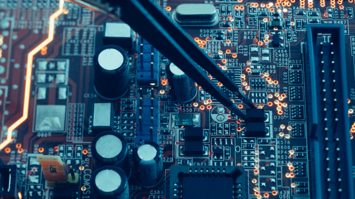
While each part has its own role, the true power of a PCB comes from how all the components on a circuit board work together. Resistors regulate current, capacitors stabilize voltage, inductors manage energy flow, transistors process signals, and diodes control direction.

This level of coordination requires careful design and precise assembly. That is where experienced manufacturers like Nova Engineering make a difference. By ensuring that every component is correctly placed and properly integrated, they help create circuit boards that perform reliably in real-world applications.

The Bigger Picture for Modern Electronics

From everyday consumer devices to advanced industrial systems, the performance of electronics depends on the quality of the components on a circuit board and how well they are assembled. Even the smallest detail can impact overall functionality.

As technology continues to evolve, the demand for high-quality PCB assembly will only grow. Understanding how these components work together not only builds appreciation for modern electronics but also highlights the importance of choosing the right manufacturing partner.

When to Outsource Printed Circuit Board Assembly

Understanding when to outsource printed circuit board assembly is critical in today’s fast-paced electronics industry. As product designs become more complex and demand fluctuates, many companies are rethinking whether to keep PCB assembly in-house or partner with a trusted contract manufacturer.

Outsourcing isn’t just about reducing costs—it’s about aligning your capabilities with your strategic goals. Done right, it enables faster production, fewer quality issues, and a more agile response to changing market needs.

The High Cost of In-House Assembly

Building and maintaining an in-house assembly line requires substantial investment. From specialized equipment like pick-and-place machines and reflow ovens to ongoing technician training and quality assurance systems, the operational burden is high. This infrastructure also needs to evolve alongside rapid changes in PCB technology.

One of the clearest signs of when to outsource printed circuit board assembly is when these costs begin to outweigh the value of keeping production internal. Contract manufacturers like Nova Engineering have already made those investments—and they spread them across multiple clients, lowering the cost per unit. Outsourcing lets you tap into that infrastructure without having to build it yourself.

Indicators It’s Time to Consider Outsourcing

There’s no one-size-fits-all answer to when to outsource printed circuit board assembly, but several signs can indicate it’s time to shift to an external partner:

  • Increased lead times due to resource limitations or equipment bottlenecks 
  • Inconsistent quality or higher failure rates on delivered boards 
  • Delayed product launches from stretched internal teams 
  • Difficulty sourcing components or keeping up with inspection requirements 
  • Frequent demand fluctuations that strain production planning 

If any of these sound familiar, outsourcing can relieve pressure and improve output reliability.

Benefits of Contract Manufacturing Partnerships

Understanding when to outsource printed circuit board assembly is key to unlocking the advantages of a reliable contract manufacturing relationship. Partnering with a trusted PCB assembly provider opens the door to specialized capabilities that might not exist in-house. Contract manufacturers are constantly upgrading their tools, certifications, and knowledge to meet industry demands—from aerospace to medical and automotive applications.

When you outsource to an experienced manufacturer, you gain access to:

  • Advanced manufacturing techniques like fine-pitch BGA placement or HDI 
  • Cleanroom and ESD-controlled environments for sensitive electronics 
  • Dedicated quality control systems, including AOI, X-ray, and functional testing 
  • Knowledge of regulatory compliance, such as IPC-A-610, ISO 9001, and RoHS 

These advantages are especially valuable when you’re scaling up, launching a new product, or handling complex board designs that require consistent precision.

Preserving Internal Focus and Speed

One of the most overlooked benefits of outsourcing is that it lets your engineering and product teams stay focused. Knowing when to outsource printed circuit board assembly can help ensure internal resources aren’t tied up solving manufacturing issues, which often delays development timelines.

By outsourcing PCB assembly, you free up key personnel to do what they do best—designing, testing, and iterating on new innovations. This clearer focus can accelerate development cycles and reduce time to market—an increasingly valuable advantage in competitive product categories.

Building in Flexibility for Growth

As demand changes, so should your production strategy. Rigid in-house operations often struggle to keep pace with variable order sizes, evolving product specs, or sudden market shifts. Knowing when to outsource printed circuit board assembly helps you build flexibility into your business model.

Contract manufacturers can adapt quickly to changing volumes or requirements. Whether you’re producing hundreds or tens of thousands of boards, they offer scalable capacity without the need for internal investment or delays.

A Strategic Move Toward Smarter Manufacturing

Outsourcing printed circuit board assembly isn’t a shortcut—it’s a strategic choice that allows companies to grow more efficiently. Knowing when to outsource printed circuit board assembly matters most when your team is spread too thin, production costs are rising, or your technology is falling behind, and it’s time to evaluate your options.

A qualified contract manufacturer like Nova Engineering can help you lower risk, maintain high quality, and speed up delivery—while your team stays focused on innovation. For many companies, that’s the difference between staying competitive and falling behind.

6 Educational Circuit Board Facts That Power Modern Electronics

From the smartphone in your pocket to the industrial systems that run factories, circuit boards are at the heart of nearly all electronic technology. Yet most people know surprisingly little about what makes these boards work—or why they’re so important. Here are six essential circuit board facts that offer insight into the design, functionality, and innovation behind today’s printed circuit boards (PCBs).

1. Circuit Boards Simplify Complex Electrical Systems

One of the most important circuit board facts is that PCBs reduce the need for bulky wiring. Before PCBs, electronics were assembled using point-to-point wiring, which was not only messy but also prone to human error and difficult to replicate at scale. Printed circuit boards replaced this with pre-designed copper traces, streamlining the design, reducing manufacturing errors, and making mass production of electronics feasible.

PCBs serve as both the physical structure and the electrical connection platform for components such as resistors, capacitors, diodes, and microchips—all neatly arranged on a single board.

2. There Are Several Types of PCB Configurations

Another essential entry in circuit board facts: not all PCBs are the same. The type of circuit board used depends on the application’s complexity and requirements. Common types include:

  • Single-layer PCBs – Ideal for simple electronics like calculators and LED lights

  • Double-layer PCBs – Used in more advanced consumer electronics

  • Multilayer PCBs – Found in servers, industrial equipment, and advanced computing

  • Rigid-flex PCBs – Used in aerospace, medical, and compact consumer devices

Each type supports specific performance needs, cost levels, and design constraints.

3. PCBs Can Have Over 50 Layers

One of the more surprising facts is that advanced PCBs can consist of more than 50 layers of copper and insulating material. These multilayer boards are essential for devices that require high-speed data transmission, complex signal routing, or power distribution across multiple channels.

High-performance computers, 5G infrastructure, and aerospace systems rely on these densely packed boards to maintain reliability and speed without increasing the device size.

4. Surface Mount Technology Has Replaced Older Techniques

Decades ago, through-hole technology was the standard for mounting components on a PCB. Today, Surface Mount Technology (SMT) is the dominant method. SMT allows components to be mounted directly onto the surface of the board, enabling:

  • Smaller board sizes

  • Faster automated assembly

  • Higher component density

This evolution in assembly methods is one of the most important circuit board facts influencing modern electronics design.

5. Circuit Boards Are Designed Using Specialized Software

Designing a circuit board isn’t done by hand—it requires precision software tools. Engineers use computer-aided design (CAD) programs like Altium Designer, Eagle, or KiCad to lay out the copper traces, component placement, and via locations. These tools generate Gerber files, which are the standard file format used by manufacturers to fabricate PCBs.

This digital design-to-manufacturing workflow ensures every printed circuit board meets exact specifications and performance requirements.

6. Clean Manufacturing Matters More Than You Think

One of the lesser-known but critical circuit board facts is how important cleanliness is during manufacturing. Dust, oils, or static discharge can compromise conductivity or damage sensitive components. That’s why PCB manufacturing facilities often follow strict environmental controls, similar to cleanrooms used in semiconductor fabrication.

Maintaining a controlled environment ensures higher reliability, longer board life, and reduced failure rates—especially in high-stakes industries like medical, military, or aviation.

Why These Circuit Board Facts Matter

Understanding these circuit board facts helps demystify the technology that powers modern life. Whether you’re designing consumer electronics, industrial systems, or mission-critical devices, knowing how PCBs function—and how they’re evolving—helps you make smarter design, sourcing, and manufacturing decisions.

At Nova Engineering, we specialize in assembling reliable, high-performance circuit boards for a wide range of industries. From prototype to production, we ensure every layer, connection, and component is built with precision and care.

Why are Circuit Board Assemblies Printed?

Before modern advancements in electronics, connecting components in a circuit was a manual and error-prone task. Engineers relied on point-to-point wiring to create circuits inside radios, computers, and early appliances. This method was time-consuming, difficult to repair, and prone to short circuits. Everything changed when the concept of a circuit board printed with conductive paths emerged.

The shift to printed circuit boards (PCBs) revolutionized electronic design and manufacturing. Instead of hand-wiring every connection, engineers could now design a board with etched copper traces to automatically route electricity between components. This innovation drastically improved efficiency, reliability, and scalability.circuit board printed- nova engineering

The Origins of Printed Circuit Boards

In 1936, Austrian engineer Paul Eisler introduced the first concept of a circuit board printed with copper pathways. He created a non-conductive base material with a printed copper circuit on top, which allowed components to be soldered onto predefined traces. While early versions looked nothing like today’s compact multilayer PCBs, the foundational idea remains the same.

The transition to printed technology laid the groundwork for the mass production of electronic devices. It also reduced human error and allowed for more precise circuit design, which is essential in everything from consumer electronics to aerospace systems.

How Is a Circuit Board Printed Today?

Modern PCB technology begins with a simple sheet of copper laminated onto a fiberglass-reinforced epoxy material (commonly FR4). The steps to manufacture a printed circuit board are precise and controlled to ensure quality and consistency.

1. Design and Gerber Files

The first step in creating a circuit board printed design is using computer-aided design (CAD) software. Engineers generate what’s known as Gerber files—digital blueprints that detail the layout of copper traces, pads, vias, and holes. These files drive every phase of manufacturing.

2. Drilling

Once the layout is finalized, the board undergoes a drilling process to create holes that will later hold through-hole components or vias. Each circuit board printed design includes precision-placed holes, created by computer-guided drills based on the Gerber file.

After drilling, the board is cleaned to remove any dust or debris, ensuring proper adhesion of materials in later steps.

3. Creating Copper Traces (Etching)

To create the conductive pathways, a photosensitive resist layer is applied to the copper surface. A light is used to expose only the desired circuit pattern. After exposure, the unprotected copper is removed using a chemical etching process, leaving behind the intricate network of copper traces.

This etching step is what transforms a blank copper sheet into a PCB with a custom circuit layout.

4. Solder Mask and Silkscreen

Once the traces are etched, a green (or sometimes blue, red, or black) solder mask is applied. This layer insulates the copper traces and prevents solder bridges between components during assembly.

The silkscreen layer is printed next. It provides labels, part numbers, and component identifiers directly on the circuit board printed surface, guiding technicians during assembly.

The Value of Printed Circuit Board Assemblies

A PCB with accuracy enables faster assembly, more compact device designs, and easier mass production. Whether used in smartphones or spacecraft, printed circuit boards provide the foundation for electrical functionality and performance.

Printing circuit boards also enables automation in the next stage: PCB assembly. Using automated pick-and-place machines, manufacturers can quickly place thousands of components onto a circuit board with pinpoint accuracy. Combined with reflow soldering and inspection, this results in highly reliable electronic systems.

The Role of Printing in Modern PCB Manufacturing

Today, the term printed circuit board refers not only to the physical traces on a PCB but also to the broader manufacturing process that allows for miniaturization and performance in advanced electronics. As devices become smaller and more powerful, printed circuit board technology evolves alongside them.

From its origins in early radios to powering high-speed computers, the innovation of having a circuit board printed with precise paths has transformed electronics forever. For engineers and manufacturers, it remains one of the most essential building blocks of any electronic design.

Understanding the PCB Environmental Impact: What You Need to Know

As electronics become more essential to daily life, so does the need to understand the pcb environmental impact. Printed circuit boards (PCBs) are foundational to nearly all electronic devices, but their production and disposal can have significant environmental consequences. From material sourcing to end-of-life management, each stage in the PCB lifecycle plays a role in shaping its ecological footprint.

This article explores how the PCB manufacturing process affects the environment and what the electronics industry is doing to minimize that impact.

Materials and Sourcing: The Environmental Cost of Raw Inputs

The environmental journey of a PCB begins with its materials. Substrates like FR-4, commonly used in board construction, are made from fiberglass-reinforced epoxy — a material that involves hazardous chemicals and energy-intensive manufacturing. While effective and durable, these traditional substrates contribute to environmental strain.

Copper is another key material. As the main conductor in PCBs, it’s essential for functionality but also requires significant mining and refining. These operations consume large amounts of energy and release emissions into the environment. Recycling copper is a more sustainable solution, helping reduce the pcb environmental impact by minimizing the need for new resource extraction.

Solder, once made predominantly with lead, has shifted toward lead-free alternatives to reduce toxicity. Even so, lead-free solders can contain other metals that require careful disposal and recycling procedures to prevent environmental harm.

Manufacturing: Energy and Emissions

Manufacturing PCBs consumes a notable amount of energy, particularly during high-temperature processes like reflow soldering. These ovens and other assembly equipment often rely on non-renewable electricity sources, further amplifying the pcb environmental impact.

Emissions are also a concern. Processes such as soldering and cleaning can release volatile organic compounds (VOCs) and other airborne pollutants. To reduce emissions and energy use, manufacturers are turning to:

  • Energy-efficient machines and production systems

  • Smarter ventilation and HVAC solutions

  • Renewable energy sources where available

These upgrades not only reduce carbon footprints but can also cut operational costs over time.

Waste and E-Waste: Managing Byproducts and Obsolescence

PCB production generates a range of waste, including trimmed materials, defective boards, and excess components. More concerning, however, is what happens when PCBs reach the end of their lifecycle. Improper disposal contributes to the growing global issue of e-waste, with toxic materials leaching into soil and groundwater.

Recycling is a key solution. Valuable metals such as gold, silver, and copper can be recovered from old boards. Many countries now regulate e-waste disposal, requiring manufacturers and consumers to participate in proper recycling programs. Additionally, designing PCBs for easy disassembly can significantly increase the effectiveness of recycling and reuse efforts while helping to reduce overall pcb environmental impact.

Chemicals and Contamination

The assembly process for PCBs involves a range of chemicals — from fluxes to cleaning agents — that can pose environmental risks. If mishandled, these substances may contaminate water sources or soil. Some also pose health risks to workers when not properly managed.

To counter this, many manufacturers are adopting:

  • Eco-friendly fluxes and solvents

  • Automated chemical handling systems

  • Compliance with environmental regulations such as RoHS and REACH

These strategies reduce pollution and improve worker safety without sacrificing quality or performance.

Transportation and Supply Chain Footprint

In today’s global supply chains, PCBs and their components often travel long distances before reaching their destination. This logistics process contributes to carbon emissions, especially when relying on air freight or diesel-powered vehicles.

Manufacturers are working to reduce this impact by consolidating shipments, choosing more local suppliers, and using electric or low-emission transport options. These efforts support a smaller pcb environmental impact while streamlining operations.

End-of-Life Responsibility and the Ongoing PCB Environmental Impact

The environmental footprint of a PCB doesn’t end at manufacturing. When electronic devices are discarded, their circuit boards often go with them. Without proper recycling, these materials may sit in landfills for decades, slowly leaching harmful substances.

End-of-life strategies are now a critical part of the electronics industry’s shift toward sustainability. Take-back programs, local recycling centers, and international regulations all aim to manage e-waste responsibly and reduce long-term pcb environmental impact. Manufacturers are also investing in design improvements that make disassembly and component reuse more efficient and cost-effective, supporting a circular economy approach in electronics production.

Building a Greener Electronics Industry

Reducing the pcb environmental impact requires a full-lifecycle approach — from sustainable material sourcing to energy-efficient manufacturing and responsible disposal. Manufacturers that embrace eco-friendly practices not only help protect the environment but also meet growing consumer and regulatory demands for sustainability.

As awareness grows, so does innovation. With ongoing efforts to design cleaner, smarter, and more recyclable PCBs, the electronics industry is actively working toward a more sustainable future — one component at a time. At Nova, we’re proud to contribute to that future by integrating sustainable materials, energy-conscious production methods, and responsible end-of-life strategies into every stage of our PCB manufacturing process.

The History of Circuit Boards: From Invention to Innovation

The history of circuit boards is a fascinating journey through time, technology, and innovation. What began as a rudimentary method for connecting electrical circuits has evolved into a highly precise, miniaturized process that powers nearly every modern electronic device. At Nova Engineering, we specialize in high-quality PCB assembly in Denver, Colorado, and we take pride in the legacy that brought us to where we are today.

The Early Days: The First Concept of a Circuit Board

The history of circuit boards begins in the early 20th century with Albert Hanson, a German inventor who, in 1903, filed a patent for a method of constructing flat, layered circuits. While rudimentary, this early invention laid the groundwork for what we recognize today as the printed circuit board (PCB). Hanson’s design included conductive foil paths mounted to insulating boards, a clear precursor to today’s multi-layered systems.

In 1927, American inventor Charles Ducas advanced this idea by printing conductive paths directly onto a flat wooden board using stencil and conductive ink. His creation marked the first true “printed” circuit board and introduced the concept of streamlined electrical connectivity without bulky wires.

Paul Eisler and the Modern PCB

While many contributed to the development of PCBs, Paul Eisler is widely credited with inventing the modern version. In the 1930s and 1940s, Eisler applied his knowledge of printing to electronic circuits while working in England. His innovation, printing conductive traces onto a board rather than hand-soldering wires, revolutionized electronic manufacturing. His technology was first used in British military radios during World War II.

By 1943, more advanced methods of etching circuits onto copper emerged. These early circuit boards were printed onto glass-reinforced, non-conductive substrates—a technique that gained public exposure in 1948 when the U.S. military released the technology for commercial use. This milestone marked a new era in the history of circuit boards and paved the way for mass production.

The Age of Transistors and Miniaturization

History of Circuit BoardsThe 1950s brought a major shift in the history of circuit boards with the advent of transistors. Unlike vacuum tubes, transistors were small, reliable, and efficient. This innovation allowed PCBs to shrink in size while increasing in complexity and reliability. Electronics could now be manufactured for home use, enabling the rise of consumer electronics.

During the 1960s, double-sided circuit boards became common. One side held identification printing and the other housed electronic components. This further improved layout efficiency and performance.

Surface Mount Technology (SMT) and the Rise of Automation

One of the most important developments in the history of circuit boards came in the 1980s with the introduction of Surface Mount Technology (SMT). SMT allowed components to be mounted directly onto the surface of the board, removing the need for drilling holes as in traditional through-hole technology. This reduced assembly time, improved reliability, and enabled further miniaturization.

At Nova Engineering, our PCB assembly process includes both surface mount and through-hole technologies, depending on the specific needs of your design. Our experienced team has been at the forefront of innovation for over 35 years, and we’re proud to continue pushing the boundaries of what PCBs can do.

The Modern Era of PCB Assembly

Today, PCBs are incredibly advanced. They often include multiple layers, solder masks, silkscreens, and precision-machined traces. Materials such as fiberglass, copper, and gold plating are commonly used. Whether it’s in smartphones, medical devices, or aerospace systems, modern PCBs are the silent workhorses behind the world’s most sophisticated technology.

With the rapid growth of Internet of Things (IoT), artificial intelligence (AI), and wearable devices, the history of circuit boards is still being written. PCB design and assembly must now meet increasingly complex demands, including ultra-compact designs, high-speed data transmission, and energy efficiency.

Nova Engineering: Proud to Build the Future

At Nova Engineering, we honor the history of circuit boards by delivering exceptional service in PCB assembly, including turnkey, consigned, and partially consigned builds. With three fully equipped production lines and a dedicated prototype line, we welcome projects of all sizes and complexities.

We’ve partnered with customers for over three decades to build the technology they’re passionate about. Our strong vendor relationships and expert team ensure competitive pricing and unmatched quality.

If you’re ready to bring your next PCB project to life, contact Nova Engineering today to request a quote.