Top 5 Latest Equipment You Need for Assembling Your Boards

While making PCBAs is a fun task, learning how the brains of all electronics are created offers joy and a sense of accomplishment. Each step of the assembling process is carefully thought out to produce a board that works flawlessly. Additionally, as electronics become more sophisticated, PCB manufacturing equipment is increasing and becoming more fascinating than ever.

Solder Paste Printing Machine

Solder paste is applied to the board as the initial step in PCB assembly. Usually composed of tin, lead, and silver alloys, solder paste is a grey-coloured goo formed from a combination of very microscopic metal particles. Consider it as the glue holding your finished board together. Components wouldn’t adhere to your bare board without it.

The PCB is covered with a stencil before the paste is applied. A PCB stencil is a piece of stainless steel with tiny laser-cut holes that allows solder paste only to be applied to the SMD pads, which are the board parts where the component connections will eventually be located on the finished PCB.

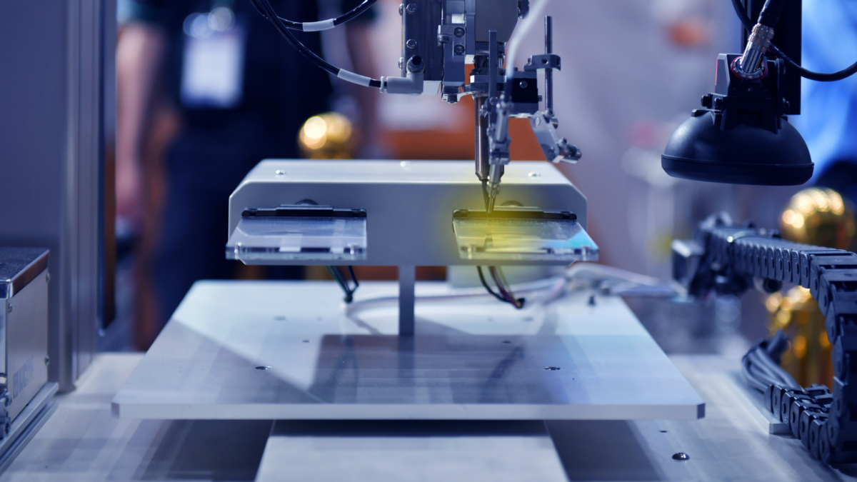
Glue Dispensing Machine

The glue dispensing machine uses glue dots on the PCB before component insertion to hold the component bodies until the leads and contacts are connected. This is crucial for reflow soldering or double-sided wave to prevent component drop-off and wave soldering, where the force of the solder wave may remove bigger components.

Reflow Soldering Machine

The most used soldering method for PCB assembly is reflow soldering. The assembly is transported via a conveyor via a lengthy, enormous oven called the reflow soldering machine once the board has been fully populated with components. As the PCB boards move through several temperature-controlled zones, the solder paste melts and steadily hardens to make reliable electrical connections between the component pads and their corresponding components.

The circuit board is moved along a conveyor system through the equipment’s various temperature zones. The solder paste is dried, heated, melted, wetted, and chilled before the components are soldered to the printed circuit board. The main component of reflow soldering is using an external heat source to heat the solder, causing it to melt, flow, and re-infiltrate the circuit board.

Automated Optical Inspection (AOI)

The boards have now been assembled, and testing and inspection are next. Automatic visual inspection is more crucial than ever due to the rise in the complexity of PCB boards. Even though you can still try to use your naked eyes to discover errors, manual inspection is ineffective for mass production since workers quickly become worn out, and errors are more likely to be overlooked. Testing PCBAs is essential in PCBA manufacture to prevent expensive re-manufacturing costs and material waste. AOI systems identify issues early in the production cycle, allowing for the modification of methods or the correction of specific boards.

AOI systems can complete tests formerly done by humans but much more quickly and accurately by using optical technologies to detect errors. The AOI machine uses high-resolution cameras to capture the board’s surface and create an image for analysis.

Functional Validation Test (FVT)

Before shipment, completed PCBs must pass Functional Validation Testing (FVT), which is the last phase. We are no longer merely looking for physical flaws like solder bridges or tombstones. The board is instead loaded with software, and we are testing to see if it will function when utilised in whatever application our customers have in mind.

Conclusion

Likely, components won’t be manually soldered when many PCBs need to be created. Expert assembly companies steps in to assist with the fabrication of both the bare boards and the assembly of all the parts into the Printed Circuit Boards, or PCBs.

Top 5 Latest PCB Board Assembly Equipment

The process of assembling a PCB board has become both increasingly precise and technologically advanced. Whether you’re just starting to build a PCB board or you’re working with an established assembly company, the latest PCB board assembly equipment can take efficiency and accuracy to the next level. With each new breakthrough in assembly technology, the process becomes faster and more reliable, providing the foundation for cutting-edge electronics.

Here’s a rundown of the essential equipment needed for PCB board assembly in 2024:

1. Solder Paste Printing Machine

In PCB assembly, applying solder paste is the crucial first step. This paste, often a mix of tin, lead, and silver, acts as an adhesive, allowing components to securely bond to the board. The solder paste printing machine ensures a precise and consistent application of this paste onto the board’s SMD pads through the use of a stainless-steel stencil.

Today’s solder paste printers come equipped with enhanced precision capabilities, driven by AI algorithms that adapt to each board’s layout. These machines minimize waste and guarantee that solder is applied uniformly, which is vital for the success of the entire assembly process.

2. Advanced Glue Dispensing Machine

To avoid component displacement during reflow soldering, glue dots are strategically applied to the board using a glue dispensing machine. With the rapid pace of modern PCB board assembly, this machine is more critical than ever, especially for double-sided boards where components could otherwise fall off due to gravity or the force of the solder wave.

The latest glue dispensers offer adjustable speed and dispensing pressure settings, allowing manufacturers to customize glue application based on component size and layout. These features help avoid glue overflow, which can interfere with soldering and affect the functionality of the finished PCB.

3. High-Efficiency Reflow Soldering Machine

Reflow soldering remains the most widely used soldering method in PCB assembly. This process involves heating the PCB in a reflow soldering oven, where it passes through zones of increasing and decreasing temperatures. The latest reflow soldering machines feature sophisticated thermal profiling, which prevents overheating and ensures a solid bond between each component and the PCB.

Advanced models now use machine learning to monitor temperature zones and predict any potential issues before they arise. This innovation reduces the chance of defective boards and shortens the overall assembly time, which is especially valuable for large-scale PCB production.

4. Automated Optical Inspection (AOI) System

As PCB designs grow in complexity, thorough inspection becomes essential. Automated Optical Inspection (AOI) systems have become indispensable in identifying defects early in the assembly process. Modern AOI systems utilize high-resolution cameras, laser measurements, and AI-driven pattern recognition to detect issues with unmatched accuracy and speed.

The latest AOI systems in 2024 can identify even the subtlest irregularities, such as micro-cracks, tombstoning, and misalignments, which would be impossible to detect with the naked eye. These systems reduce the risk of defects reaching the final product, saving both time and material costs in the long run.

5. Functional Validation Test (FVT) Systems

Once assembly is complete, the Functional Validation Test (FVT) checks that the board performs as intended in its real-world application. Unlike earlier inspection methods, which only focused on physical flaws, FVT involves loading software onto the PCB and testing its performance within the end product environment.

The latest FVT systems offer modular testing capabilities, allowing manufacturers to quickly adapt the test parameters to different PCB designs. This flexibility is particularly beneficial as custom PCBs become more common, enabling tailored testing solutions that match the board’s end-use application.

Crafting Perfection: How Advanced Machines Revolutionize PCB Assembly

As the industry advances, manual soldering and assembly are becoming increasingly rare for large PCB production runs. With innovations in PCB board assembly equipment, companies can now build a PCB board faster and more accurately, minimizing errors and maximizing reliability. For businesses in need of high-volume, high-quality assembly, these cutting-edge machines deliver precision that meets the demands of today’s sophisticated electronics market.

How To Solder On Printed Circuit Boards

Solder is a material that manufacturers use in the printed circuit board assembly process. This material can join soft metals such as gold, copper, and silver together. Copper is the common material in the printed circuit board assembly or any electronic item.

Most commonly, manufacturers will use eutectic solder, a combination of tin and lead. This is about 63% and 37% lead, and it comes with a formulation with a minimum melting point for the combination of metals.

Properties

Different solders come with different melting points and ranges of temperatures where solid and liquid tend to co-exist together. You can also form a pasty substance as it cools, and you can find that it is very flexible. The flexible property or ductility allows the metals that join it to interpenetrate once you melt it.

It is a dense and heavy material because it has a high lead content. It also comes in several different gauges and wire diameters. For surface mount devices, a very fine one is more useful. You can also find lead-free, which comes with the formulation of tin, silver, and copper.

This does have a melting point, and you can use this commonly with electronics that use low-temperature soldering irons. Lead-free has a high melting point, which is why it can be difficult to work with. This material is also relatively new, and most people will be unfamiliar with its properties.

Printed Circuit Board Soldering

A printed circuit board holds electronic components and provides a mechanical means of holding them in a space where they connect electrically. A printed circuit board contains different resistors, active circuits, and capacitors.

The circuit board holds them together collectively and consists of several layers. The first layer you see is a green layer, a polymer called LPI. This photo image-able polymer can go down as a liquid and dry to form a solid layer. The green layer is necessary to prevent it from crossing over and shorting traces that should not connect.

Basic Technique

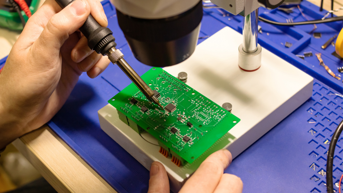
If you are manually soldering components to a printed circuit board, you must adhere to the basic technique. There are two different types of soldering iron. One has a station that controls and adjusts the desired target temperature. The other melts electronics at a fixed temperature, which you can use similarly.

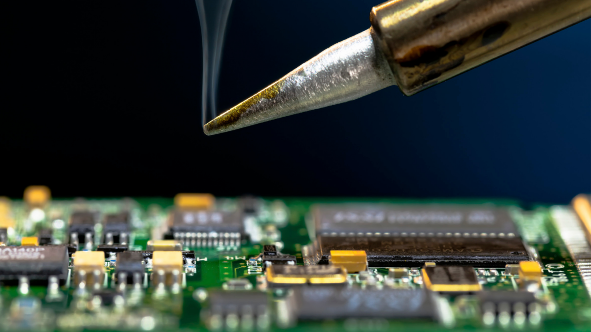
Soldering iron heat up and melt the solder on the circuit boards. When it melts and cools on the printed board surface, it cools and solidifies, fusing to the surface of the metal at a molecular level and enabling electrical conductivity within the two metal platforms.

When soldering with an iron, you can also use flux, which helps it to flow, and also provides good contact by removing oxides on the surface of the metal. Although modern flux is not toxic, you should always use a fume extractor.

Two Different Connections

You can find two different types, surface mount and through hole. Surface mount connections require manufacturers to heat components in an oven with pre-applied. This allows it to melt and join to the board’s surface. Through-hole is when you push the components through the printed circuit board hole and solder them from the other side. The solder travels across the hole to make good contact.

Final Words

As you can see, this is an essential part of the printed circuit board assembly process. It is best to resort to a professional manufacturing unit to do a perfect job. The best soldering service will use top-notch technology for clean and precise solder.

The Right Way to Solder on Printed Circuit Boards

Soldering is the most vital part of the PCB assembly process. It’s where the electrical components get attached to circuit boards. Without electrical components, no PCB would function effectively. There are various methods to sell electrical components to PCB and ensure electrical currents pass through the conductive pathways efficiently.

The main issue is that many people don’t know the right way to solder electrical components on circuit boards. Since a bunch of them are being used in factories, it can be quite tricky to pick the right one. We will discuss some of the top soldering techniques so you can choose the one that’s right for your business.

The Right Way of Soldering on Printed Circuit Boards

In the electronics world, soldering is a fundamental skill that nearly every professional must have at some point. Soldering and electronics go together like a fork and spoon.

Although people learn how to design, build, and release electronics without picking up a soldering iron, it’s still a vital part of the industry. Let’s check out a few soldering methods and techniques commonly used these days.

1.      Reflow Soldering

It’s the most common soldering method factories use today, especially for manufacturing surface mount technology or SMT printed circuit boards. This soldering method involves using a heated soldering paste to attach electrical components to the circuit board. The paste looks like molten metal, enabling professionals to connect pins and pads seamlessly. However, it results in permanent attachment.

2.      Wave Soldering

Wave soldering was once extremely popular for wave soldering. However, it’s still commonly used for surface-mount technology circuit boards. Printed circuit boards that go through the through-hole process (i.e., drilling holes in the board to fit electrical components) usually also go through the wave soldering process.

Generally, factories utilize wave soldering to produce massive PCB assemblies. The PCBs go over molten solder in a pan that looks nothing less than a wave pool. Once through, electrical components get attached to the circuit board.

Before coming in contact with the molten solder, the components are already glued to the board. Due to an additional step that reduces efficiency and somewhat increases the time and money consumption, reflow soldering replaced wave soldering.

3.      Braze Soldering

Soft and hard soldering is nothing compared to brazing. Brazing results in fortified joints between the printed circuit boards and electrical components, including transistors, inductors, and capacitors. It uses high temperatures to attach electrical components to circuit boards.

Although it’s similar to hard soldering (discussed later), brazing involves melting the underside of the metal components to get attached to the board. It causes the least thermal deformation and is one of the best soldering techniques for mass PCB production.

4.      Soft Soldering

Soft soldering is the perfect option for compact and fragile circuit board components. Soft soldering doesn’t damage the electrical components through high heat or molten solder. In this process, the temperature of the molten solder is below 400 degrees Celsius or 752 degrees Fahrenheit.

If the temperature goes over, it becomes “braze soldering”. The low-temperature technique is for smaller components prone to breaking at high temperatures or heat conditions. Although it’s suitable for small components and fragile boards, it doesn’t produce the strongest joints.

5.      Silver Soldering (or Hard Soldering)

This soldering technique also yields strong joints between components and circuit boards. However, combining metal components such as gold, silver, or brass-plated components is best. It’s used to connect and attach the same metals in other industries.

Conclusion

What type of printed circuit board you’re producing will determine the right soldering technique. Other factors influencing the soldering technique include existing capabilities, materials, and requirements.

Check which soldering technique offers the most lasting results and try to match it with your PCB requirements. Partnering with a solid PCB manufacturing company could ease the process and increase soldering efficiency.